Mountain Series (MS) Ovens Venting Do’s and Don’ts
When installing a Wood Stone Mountain Series oven there are some basic guidelines to follow regarding oven venting that will help ensure proper operation and performance of the gas burners on the oven. These guidelines will also help prevent damage to the oven’s gas and electrical components due to improper venting and installation. Damage caused by improper venting and installation is not covered by the oven warranty. This information applies to all Wood Stone Mountain Series (MS) ovens equipped with one or more gas burners.
Most Wood Stone Mountain Series ovens are built into some sort of wall structure or enclosure. This creates the potential for different venting scenarios that can be detrimental to the operation and performance of the oven burners. Here are some basic rules that to follow that will ensure a properly functioning oven installation. Illustrated examples are included below.
Rule 1
The ONLY pathway for air to enter the space beneath the oven should be at the front of the oven at the perforated opening in the oven Service Panel provided with the oven, or on ovens equipped with an optional Storage Box, through the perforations provided on the sides of the Storage Box. This will eliminate the chance of air movement or cross drafts beneath the oven that can disrupt the oven burners.
Rule 2
DO NOT block the flow of air through the front Service Panel. It is required to provide necessary combustion air to the oven burners. Airflow and service access MUST be provided from the front of the oven only at this Service Panel. DO NOT relocate the oven air intake (see Rule 1).
Rule 3
To ensure proper venting of the oven, you must use an appropriate exhaust fan as described in the Installation and Operation Manual. There must also be an adequate source of make-up air provided to your kitchen space (the room that the oven opens into). The make-up air supply should not point directly at the oven. Other than the oven Service Panel, do not provide make-up air or other ventilation into an enclosure that surrounds the oven (see Rule 1). Without proper make-up air the oven, (or any gas equipment), will not vent and operate correctly.
For additional information (and images) on how to properly vent your equipment, please refer to the Wood Stone Installation and Operation Manual for your oven.
Direct Connect Venting Examples
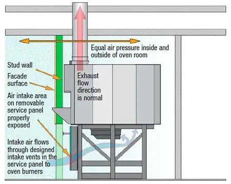
Example 1 – Acceptable Venting
This example shows a proper installation. The enclosure around the oven is completely sealed so that the only air entering the space beneath the oven comes through the oven Service Panel.
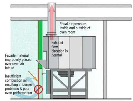
Example 2 – Unacceptable Venting
This example is not acceptable because the combustion air intake is blocked, preventing combustion air from reaching the oven burners. The burners will not function properly, and this will lead to damage of oven components.
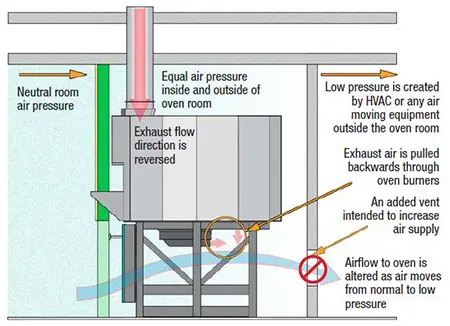
Example 3 – Unacceptable Venting
This example shows an incorrect installation where an additional vent was added to the wall behind the oven, creating an air pressure difference causing air movement beneath the oven and disrupting the operation of the oven burners. This air movement can be so severe as to cause a downdraft, pulling the exhaust down the oven flue and backwards through the burners, leading to heat damage of oven components.
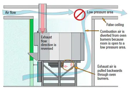
Example 4 – Unacceptable Venting
This example shows an incorrect installation where the enclosure surrounding the oven is open to the attic space above the ceiling. Air can move rapidly through the space enclosing the oven to the lower pressure area within the attic space. This can cause a downdraft situation at the oven, pulling air and heat backwards through the oven burners, leading to damage of oven components.
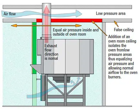
Example 5 – Acceptable Venting
This example shows a correct installation where a ceiling has been added to the enclosure surrounding the oven to correct an improper installation.
Hood Installations
In addition to the information given for installations using the direct connect venting method, the following information applies to installations where the oven is being vented using a Listed Type 1 hood.
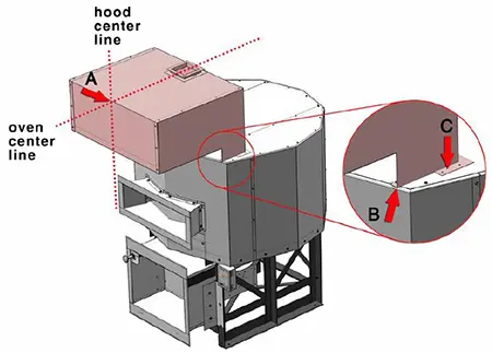
Proper Mounting Position for the Wood Stone Hood
- Center the hood from side to side on the oven (A). Note that in an MS-5, 6 or 7 model, the oven may have the round flue adapter attached. The adapter can prevent the proper positioning of the hood. The flue adapter is attached with screws. Simply remove the screws to remove the adapter if it is in the way.
- Pull the hood forward so that the notch (B), as viewed from the side of the hood, lines up with the front edge of the top of the oven.
- Secure the hood to the top of the oven using #10 self-tapping screws. The flanges on the hood are pre-drilled (C). Screw directly into the top of the oven to secure the hood.
- Attach grease-rated duct to the outlet on the hood. The hood captures over the oven flue collar and oven doorway. No connection is made to the oven flue collar.
Hood Installation with Decorative Facade Wall/Oven Enclosure
For installations where a hood is being used with a decorative facade wall or oven enclosure, it will be necessary to both seal the gap between the facade wall and the top of the oven, and the gaps at the sides of the hood between the facade wall and the front of the oven. This will prevent air from being pulled up the sides of the oven from below by the hood. It will also prevent debris, etc. from falling into the facade wall.
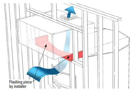
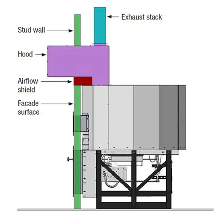
Example 1 – Acceptable Venting (see additional flashing detail below)
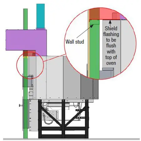
Note that the hood does extend out beyond the face of the oven. DO NOT extend the oven facade wall into the oven hood. The wall beneath the hood must stop at the top of the oven. To allow for proper function of the hood, filter removal and hood maintenance you must provide a minimum of 8 inches of clearance between the front face of the facade wall and the front of the hood.
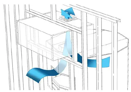
Example 2- Unacceptable Venting
No flashing has been installed so air is being pulled up the sides of the oven from beneath.
Acceptable venting – Side view of properly installed hood
Clearances
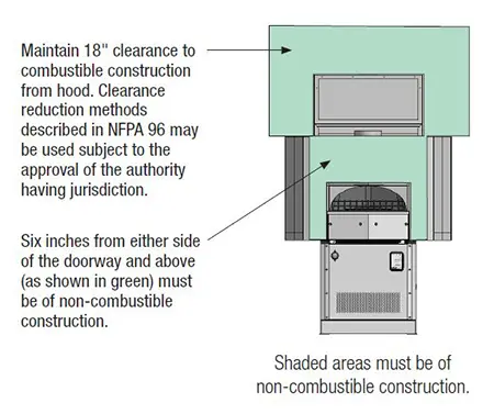
The Type 1 hood requires an 18-inch clearance to combustible construction. Clearances to limited combustibles may be reduced per NFPA 96 and/or your local codes. Approved clearance reduction methods may also be used, per NFPA 96 and/or your local codes. (These reductions are applicable to the hood and/or duct only, NOT to the oven.) Consult with your local inspector regarding approved methods.
Any facade wall 6″ to either side of the oven doorway and above MUST be of non-combustible construction with no exceptions.